Acmv System Diagram
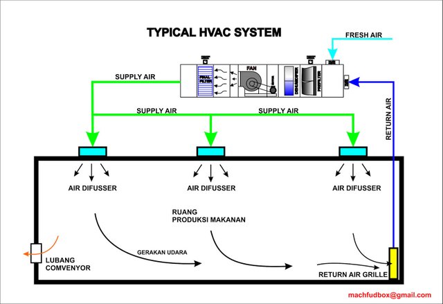
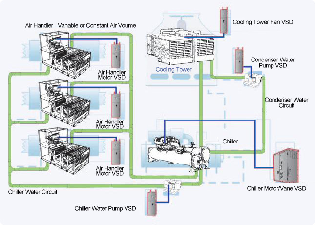
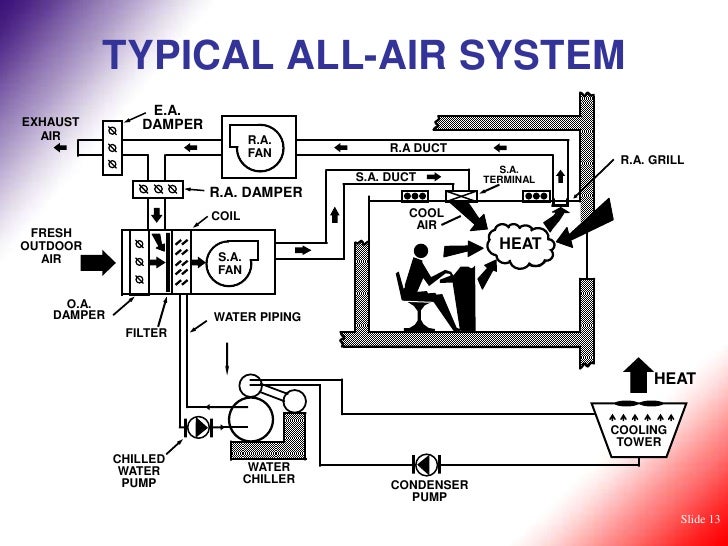
Acmv system diagram. Maintenance and Inspection. Therefore the purpose of the primary air system for active chilled beams is to. The main components of the.
The follow-up question of how we may make the motor stop running is a. The module is designed for the energy manager who has had little influence on the original design of the ACMV system but who has the responsibility of improving the energy performance of the system. However the use of 10mm to 15mm max.
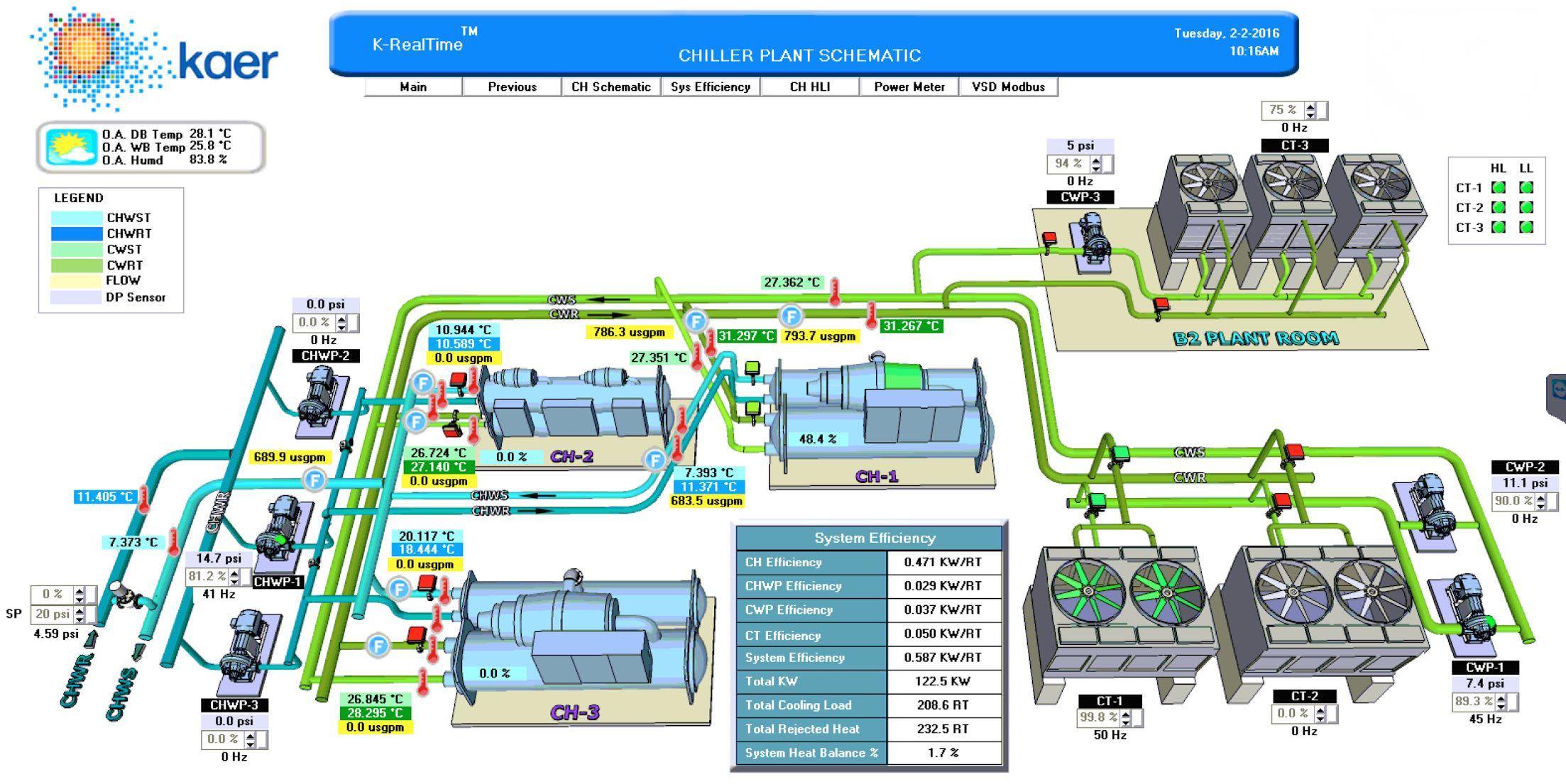
Optimization strategies of ACMV systems for enhanced performance in a chiller plant. List the steps in verifying fan power calculations. Select appropriate chilled water systems based on cooling load behavior of.
The contact in parallel with the Run switch is often referred to as a seal-in contact because it seals the momentary condition of the Run switch closure after that switch is de-actuated. Diagram 711c 3 Minimum class 1 for insulation materialbarrier lining and adhesives. Building Energy Codes Program 2.
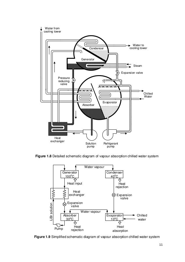
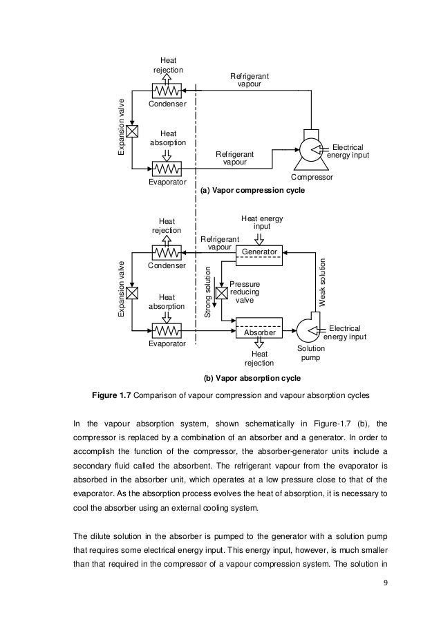
The aims of this subject are to equip students with the knowledge and skills to. The main components of the system are condenser refrigerant expansion valve evaporator absorber generator solution heat exchanger and solution pressure reducing valve. A detailed schematic diagram of such a system is shown in Figure-18.
Diagram 711b 3 i Insulation material for pipework together with vapour barrier lining and adhesives shall when tested in accordance with the methods specified in this Code. Energy efficient design and optimisation of the ACMV system contribute significantly in reducing energy consumption and achieving cost savings. Electrical Mechanical and Piping Diagram.
HVAC heating ventilation and air conditioning plans refer to the drawings made by specialized engineers that include all the details needed to create set up and maintain the heating and cooling system in a building. Air Filtration Humidity control load calculation and efficiency.
System the primary air system must also maintain the dew point of the indoor air below the surface temperature of the chilled beam to avoid moisture from condensing on the coil and dripping into the space.
A detailed schematic diagram of such a system is shown in Figure-18. Even after water levels fall contaminants will remain in the duct and lead to poor air quality as well as low performance of the heatingcooling system. A flood for example can lead to dirty contaminated water getting inside the air ducts and making them filthy. And when it does it can lead to problems with your ACMV system. 1 Deliver at least the required amount. The main components of the system are condenser refrigerant expansion valve evaporator absorber generator solution heat exchanger and solution pressure reducing valve. Select appropriate chilled water systems based on cooling load behavior of. The subject will cover the use of a psychrometric chart and pressure enthalpy diagram to evaluate and analyse the performance of the air conditioning system. Diagram 711c 3 Minimum class 1 for insulation materialbarrier lining and adhesives.
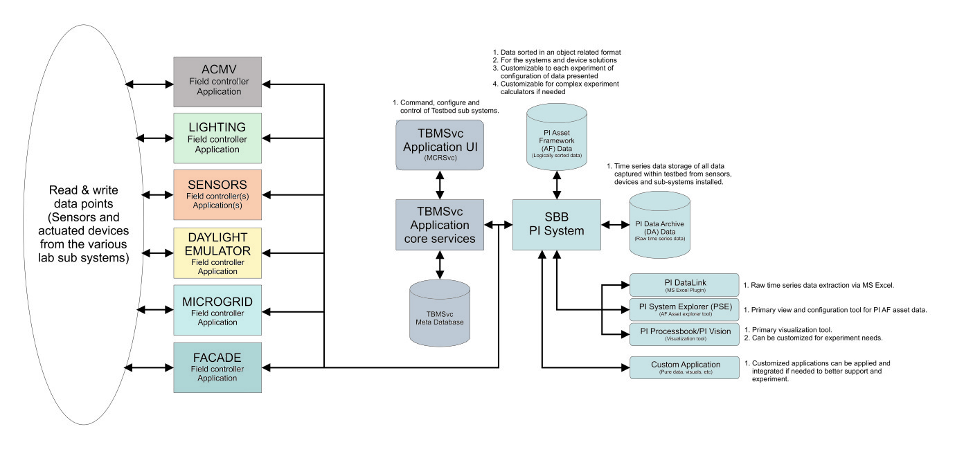
Various types of ACMV systems energy saving and optimization strategies will be explored. The testbed rooms are also heavily instrumented and National Instruments data acquisition platforms are used to. Therefore the purpose of the primary air system for active chilled beams is to. Name high impact energy code items related to HVAC equipment and controls. The HVAC plans are quite important and are developed once the buildings floor plans have been completed. Optimization strategies of ACMV systems for enhanced performance in a chiller plant. Identify important HVAC controls including economizers.












Post a Comment for "Acmv System Diagram"